In today's world, storage batteries are playing an important role, generally, as a backup/ standby power to many applications.like telecom sector, computer application to protect from data loss, etc.
Battery Chargers are basically automatic D.C. Power Sources meant to feed the connected load and simultaneously charge the connected Battery, thereby maintaining it continuously healthy &ready to feed the load in an emergency situation of A.C.Supply failure. This arrangement ensures an uninterrupted D.C. Supply to the connected load at all times - by the battery Charger in case of A.C. Power Supply availability orby the Battery in case of failure of A.C.Power Supply.Batteries make available this power source for the successful operation of switching and control devices in power protection system.
But the question arises is “do batteries will always operate when needed to operate?” If yes then the battery should be in good condition always so that it can operate during a power failure and it can be maintained through regular inspection, maintenance and testing of batteries.
If regular inspection or testing is not done then there are many things which can actually reduce the working life of a battery, some of these are listed below
·Absence of proper ventilation
·Deterioration of connections & Leakage
·Variation in voltage from cell to cell
·Battery charger settings
·. Cell post damage
Testing should be done in accordance to, firstly it ensures that the batteries meet the qualifications of both manufacturer and consumer and secondly it provides a reference point for comparison for future testing.
Here testing can be divided into two subgroups
1.Performance testing
2.Qualification testing
Performance testing provided the data about the present condition of the battery, working voltage, capacity, etc and also provides information about any problem in battery which is required to meet with working of the system.
Qualification testing is done to ensure that the capacity of the battery is sufficient or not to meet the system requirements.
Maintenance requirements involve both periodic maintenance and periodic testing. Maintenance includes visual inspection, checking and restoring electrolyte (water) levels, measuring individual cell specific gravity temperature and voltage readings, cleaning and retorquing terminal connections, etc.
Above mentioned tests require some instruments and they are
1.Multimeter
2.Digital hydrometre
3.megger
4.Dc load bank
5.internal resistance testing kit
6.hydrogen gas detection kit
Some common methods of battery tests are
1.Visual inspection- it includes finding location of the crack, leakage, corrosion if any.
2.Float voltage – check battery should not be grounded at either end, instead, it should float with both ends above the ground.This can be checked easily with the help of voltmeter.
3.Specific gravity measurement:- this can be measured with the help of hydrometer.The specific gravity of healthy battery should be in the range of 1.19-1.27. Because Specific gravity is a great way to know the battery’s state of charge.
4.Charging/discharging test- charging/discharging test can be done by knowing the value of current at that instant of time. If the value of current is increasing then it will be the state of charging and vice-versa.
5.Temperature testing- Temperature of battery should be maintained at a specified level, as the life of battery reduces with increase in temperature. Thermal imaging method I used for finding hot spots inside the battery, which indicates high thermal stress in the battery.
6.Impedance testing- Impedance of the battery will increase as the battery deteriorates, while conductance decreases.
7.State of charge (SOC)- it indicates how much of energy is left in a battery.
8.State of health (SOH)- It measures battery ability to deliver current when required to supply.
A stepper motor can be considered as a digital electro-mechanical device where each electrical pulse input results in a movement of shaft by a discrete angle called as step angle of the motor.
Or
Stepper motor is a brushless Dc electric motor that divides a full rotation into a number of equal steps.
As we all know, industrial motors are used to convert electrical energy to mechanical energy but they cant be used for precision positioning of an object or precision control of speed without using closed-loop feedback, that is where stepper motor comes into picture.Stepping motors are ideally suitable for situations where either precise positioning or precise speed control or both are required in the automation system.
A steppers main purpose is to rotate through a precise angler and remains at standstill condition.The speed and torque of the rotation are secondary concerns in stepper motor.Stepper motor rotates through the exact angle and stops. The angle through which the motor turns or shaft moves for each pulse is known as the step angle, expressed in degree, common step angles include 300 ,20,2.50 , etc. At low command pulse rate, the motor moves in steps but when the pulse rate is made sufficiently high because of inertia the rotor moves smoothly, as in case of dc motors.As motor speed is proportional to the rate of command pulses, it can be used for speed control.thus motor is ideally suitable to open loop position and speed control i.e there is no need of feedback sensor.
Let K= step angle(the angle through which the motor shaft rotates for each command pulse)
Then K= 360/ (no of stator phases * no of rotor teeth)
The stepper motor works on the simple basic principle of magnetic interaction that takes place between the rotor and stator, which makes the rotor move.The rotor has no windings and of salient pole type whereas stator has windings on it.The rotor may or may not have permanent magnets depending upon types of the stepper motor.There is a one-one relationship between an input pulse and step movement of shaft i.e each pulse input actuates one-step movement of the shaft.
Stepper motors are often constructed with a 3-phase stator winding similar to the conventional electrical machines.The rotors are either of the permanent magnet type or the variable reluctance type.Stepper motors are actuated by means of an external drive logic circuit.Series of the pulse voltage is applied to the input of drive circuit and as result it supplies suitable currents to stator windings of the motor to make the axis of magnetic field step around in synchronism with the input pulses.
Stepper motors can be broadly classified into three type:
1.Variable reluctance stepper motor
2.Permanent magnet stepper motor
3.Hybrid type stepper motor
Variable reluctance stepper motor:-
It works on the principle that when a magnetic material placed in a magnetic field experiences a force to align it in minimum reluctance path.
In a variable reluctance motor, excitation of the stator phase gives rise to a torque in a direction which minimizes the magnetic circuit reluctance.The reluctance torque depends upon the square of the phase current and its direction is independent of the polarity of the phase current .this type of motor can be single-stack or multi-stack motor.
Permanent magnet stepper motor:
Permanent magnet stepper motors are widely used in accurate positioning/controlling application due to their small step size.
The stator is of salient pole structure, while rotor shaft consists of a permanent magnet with toothed end caps. The stator poles are provided with windings that are energized sequentially to produce the stepping action.
The major advantage of permanent magnet stepper motor is that it doesn’t require any external exciting current, hence it has low power requirement but possesses high detent torque as compared to variable reluctance stepper motor.this type of motor has high inertia and hence lower acceleration.the step size of this type of motor is relatively large ranging from 30 to 90 as it is difficult to manufacture small permanent magnet rotor with large no of poles.
Hybrid Stepper motor:-
It combines the features of the variable reluctance and permanent magnet stepper motor.the direction of its torque depends upon the polarity of stator current.
It has wound stator poles and permanently-magnetized rotor poles.it is best suitable for small angle steps are required, like 1.8 degree,3.1 degrees etc.This type of motor achieves small step sizes easily and with a simpler magnet structure.As compared to variable reluctance motor hybrid motor requires less excitation to achieve a given torque.
Applications:-
Stepper motors are widely used in computer peripherals and office machines.In printer,graph plotter ,floppy/hard disk drives stepper motors are used.stepper motors are also used in Automobiles for closing and opening of glass windows,door latching and wiper movement.
The most common application of stepper motor is a wristwatch, synchronize clocks in railway platforms.
Advantages :-
1.Highly precise.
2.Steeper motor can produce high output torques at lower angular velocities.
3.The angular displacement can b precisely controlled without any feedback arrangement.
4.No sensor is needed for the position and speed sensing.
Multimeters as the name suggest meters that used to measure multiple quantities with the same instrument. The most basic multimeters measures voltage, current, and resistance,because it is used for measuring resistance(ohm), current(ampere) and voltage(volt) can be also called as AVO meter.
Multimeters can be divided into two parts,namely Analog multimeters and Digital Multimeter.
Analog Multimeters:-
Analog multimeters were first of its type to be manufactured,but due to latest technological development now it is of less use.However, despite of such developments, its importance can’t be neglected.
Basically ,an analog multimeter is a PMMC meter.Its working principle is based on the d’Arsonval galvanometer principle and measures current,voltage and resistance of any circuit.It consists a needle to indicate the measured value on the scale.Analog multimeter works on the principle that like magnetic poles repel each other.A coil moves in a magnetic field when current passes through the coil.The indicating needle is fastened to the coil.When current passes through the coil,a deflecting torque is produced due to which the coil rotates by some angle and the pointer moves over a graduate scale.A pair of hair springs attached to the moving spindle to provides the controlling torque .In a multimeter ,the galvanometer is left zero-type instrument ,i.e needle rests to the extreme left of the scale.
To measure dc current ,the meter acts as an ammeter with a low series resistance .To measure high current a shunt resistor is connected in such a way that the current flow through the meter is not more than the maximum value .by adding a shunt resistance ,an analog multimeter can be used as milli-ammeter or ammeter.
For dc voltage measurement ,the basic instrument becomes a dc measuring instrument .By adding a multiplier resistance ,an analog multimeter can measure the voltage from milli-volts to kilovolts and this meter works as millivoltmeter,voltmeter or kilo voltmeter.
By adding a battery and resistance network,this instrument works as ohm-meter.The range of the ohm-meter can be changed by connecting the switch to a suitable shunt resistance.By selecting different values of shunt resistance ,different ranges can be obtained.
Below the basic block diagram of an ammeter is given
Here we are using two switches namely S1 and S2 to select the desired meter. Additional range-selector switches may be used to select individual ranges required in reading amperes,volts, and ohms.
To measure an ac voltage or current by measuring instrument a rectifier is used.
Advantages :
All measurements are possible by using one meter only.
Increase or decrease in signal levels can be observed.
Disadvantage:
·Analog meters are bulky in size.
·They are heavy and costly .
·The pointer movement is slow ,can’t be used to measure voltages with frequencies greater than 50 HZ.
·Inaccurate due to the effect of earth’s magnetic field.
Auto Transformer :-- A transformer in which a part of the winding is common for both primary and secondary circuits, is called an auto transformer .Where as in two winding transformer both windings are electrically isolated but magnetically coupled .
Some times we need to transfer Maximum power from source side to load side ,then we have to apply Maximum Power Transfer Theorem in given circuit . But to gain Maximum Power Transfer at load side we have to compermise with efficiency of the system ,i.e during Maximum Power Transfer overall efficiency of the circuit is only 50% .
Let a circuit in which we have to find a condition for Maximum Power Transfer
What is Phantom loading ?? When the current ratings of meter under test is very high,a test with actual load arrangements consumes considerable waste of power. To avoid this Phantom loading is used:- Phantom loading consist of supplying the pressure circuit(voltage coil) from rated voltage supply and the current circuit from a low voltage supply. Thus it is possible to circulate the rated current through with the current circuit with low voltage supply as the circuit impedance is very low.
The total power consumed by Phantom loading is very small as compared to direct loading.
In Phantom loading arrangement energy consumption in the calibration test of watt- meter is reduced because of the absence of load in the test.
Concept
of smart grid is quite in the news and market but majority of the
people actually don’t know that what exactly are the things which make a
grid smart?
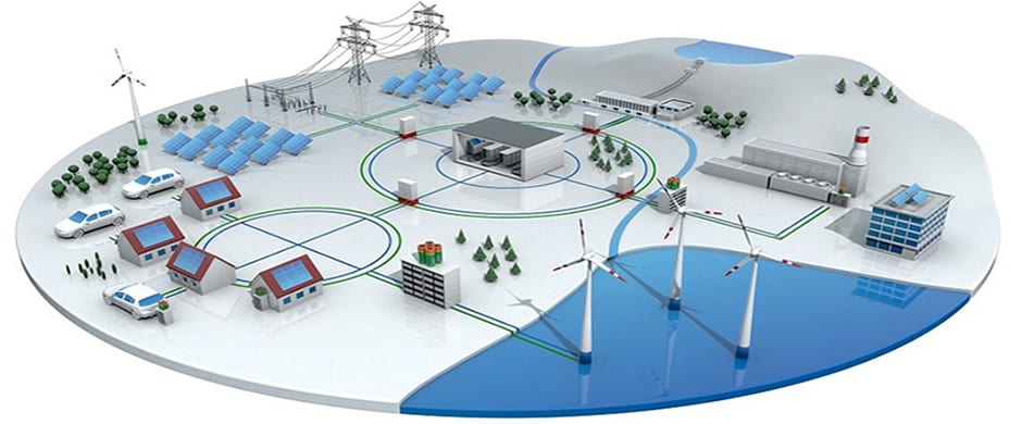
The term “Grid” refer to an “Electric Grid”
basically describes a complete network which includes transmission
lines, transformers, distribution substation all accessories that are
used for delivery of electricity from generation plants to home and
commercial scale.
The
very first grid was built in decade of 1885-1895 and the with the
passage of the time number of grids kept on increasing that’s why by now
there are about more than 9200 grids all over the world which are
providing about 1 million Megawatt power to the consumers.
As
evolution has a direct relation with time so for an efficient
functionality of grid, digital technology has been introduced in grid
system. This new digital technology enables two way communications which
guarantees the direct link between utilities and all consumers.
What is a Smart Grid Then?
In
simple words, an automation system between utility and consumers. This
smart grid consist of advance digital system, automation, computer and
control which make sure to perform a duplex “two way” communication
between the power provider and load consumer.
In a typicalelectrical grid system,
electricity provider only will know the power failure when a costumer
call them. But in case of smart grid system, if electric supply fails,
service provider will automatically respond to the affected area because
the components of smart grid provides enough data i.e. from the power
transformer, maintransmission and distribution systemand finally, to thehome supply system(you may say the utility meter).
What Things Make a Grid “Smart”?
According
to the Department of Energy (United States), Four types of advance
technology will transform a typical electrical grid intoSmart Gridwhich are as follow:
Fully automated and Integrated two way communication between the overall components of an electric grid.
Automatic Control for power distribution, faults and repairs.
Advance management panel, decision support software and mechanism.
Accurate sensing and measurement technologies.
Upgraded
technology of smart grids has well-organized automation equipment and
control system, whose response is accurate to meet the rapidly
increasing demand for electricity. Time when these smart grids were not
implemented all utilities companies were bound to send their respective
workers to take meter reading and acquire data related to consumer.
What does a Smart Grid do?
Smart grid performs lots of smart jobs. Someadvantages of a smart gridare stated follow:
Efficient Transmission and Distribution of Electric Power. Quickly restore electric power after power failure due to faults. Lower cost for operation, maintenance, management and electricity for both utilities and consumers. Lower electric power tariff and rates due to reduced peak demand. Provide better options ofintegration of renewable energyfor self power generation systems. Improve the security and protection.
Applications of a Smart Grid System.
Deployment
of Digital Technology in smart grids ensures the reliability,
efficiency and accessibility to the consumers regarding all utilities
which count towards the economic stability of the nation. Right at the
start of transition time it become perilous to execute testing, to
improve the technology by up gradation, developing and maintaining
standards on a standard threshold and also application of these
efficient grids serve all these problems
Basic applications of smart grids are
They improve the adeptness of transmission lines
Quick recovery after any sudden breakage/disturbance in lines and feeders
Cost Reduction
Reduction of peak demand
They
possess the ability to be integrated with renewable energy sources on a
large level which leads to sharing of load and reduction of load on
large scale
Summery
In
these days disruption of power supply is very common issue faced by
majority in which any fault in feeder or main distribution lines lead to
a complete blackout due to which whole system will be out of order and
functionality of industries will be stopped.
But
smart grid system has capability to secure the system on the spot by
handling emergencies because they possess the ability of automatic
rerouting in case of any fault current . Smart Grids are not only
providing the link between consumers and utilities moreover they enable
users to handle their electricity usage systematically like we use
online banking from anywhere any time.
Management
of electricity in well-organized matter will clearly lead to cost
reduction. One of the interesting application is smart meters. With the
help of smart meters we need not to wait a whole month to get
electricity bill rather we can see reading and receive bill daily online
which will obviously save money for consumers and save electricity or
power for whole country which will provide support in economical
stability of the country.
Coming
toward the precautions as this system has wide range of technical data
and equipment along with automation equipments and protocols, so most
important thing will be to ensure whether the system is properly
installed because, if there will be no loop holes in deployment of this
technology, smart grids on global level will bring revolution in power
sector same as internet did transformation in the World of IT.
Earthing and Types of Electrical Earthing | Electrical Grounding Installation (Step by Step)
Earthing, Grounding, Methods Of Earthing, Types of Earthing And Is Specifications In Respect To Earthing Of Electrical Installations
What is Grounding or Earthing?
To connect the metallic (conductive) Parts of an Electric appliance or installations to the earth (ground) is calledEarthingorGrounding.
In other words, to connect the metallic parts of electric machinery and devices to the earth plate or earth electrode (which is buried in the moisture earth) through a thick conductor wire (which has very lowresistance) for safety purpose is known asEarthing or grounding.
To earth or earthing rather, means to connect the part of electrical apparatus such as metallic covering of metals, earth terminal of socket cables, stay wires that do not carry current to the earth. Earthing can be said as the connection of the neutral point of a power supply system to the earth so as to avoid or minimize danger during discharge of electrical energy.
Good to know
Difference between Earthing, Grounding and Bonding.
Let me clear the confusion among earhing, grounding and bonding.
EarthingandGroundingis the same terms used for earthing.Grounding is the commonly wordused for earthing in theNorth Americanstandards likeIEEE, NEC, ANSIandULetc while,Earthing is used in European, Common wealth countries andBritain standards like IS and IECetc.
The wordBondingused for jointing two wires (as well as conductors, pipes or appliances together. Bonding is known as connecting the metallic parts of different machines which is not considered to be carrying electric current during normal operation of the machines to bring them at the same level of electric potential.
Need of Earthing or Grounding. Why Earthing is Important?
The primary purpose of earthing is to avoid or minimize the danger of electrocution, fire due to earth leakage of current through undesired path and to ensure that the potential of a current carrying conductor does not rise with respect to the earth than its designed insulation.
When the metallic part of electrical appliances (parts that can conduct or allow passage of electric current) comes in contact with a live wire, maybe due to failure of installations or failure incable insulation, the metal become charged and static charge accumulates on it. If a person touches such a charged metal, the result is a severe shock.
To avoid such instances, the power supply systems and parts of appliances have to be earthed so as to transfer the charge directly to the earth.
Below are the basic needs of Earthing.
To protect human lives as well as provide safety to electrical devices and appliances from leakage current.
To keep voltage as constant in the healthy phase (If fault occurs on any one phase).
To Protect Electric system and buildings form lighting.
To serve as a return conductor in electric traction system and communication.
To avoid the risk of fire in electrical installation systems.
Different Terms used in Electrical Earthing
Earth:The proper connection between electrical installation systems via conductor to the buried plate in the earth is known as Earth.
Earthed:When an electrical device, appliance or wiring system connected to the earth through earth electrode, it is known as earthed device or simple “Earthed”.
Solidly Earthed:When an electric device, appliance or electrical installation is connected to the earth electrode without afuse, circuit breaker or resistance/Impedance, It is called “solidly earthed”.
Earth Electrode:When a conductor (or conductive plate) buried in the earth for electrical earthing system. It is known to be Earth Electrode. Earth electrodes are in different shapes like, conductive plate, conductive rod, metal water pipe or any other conductor with low resistance.
Earthing Lead: The conductor wire or conductive strip connected between Earth electrode and Electrical installation system and devices in called Earthing lead.
Earth Continuity Conductor:The conductor wire, which is connected among different electrical devices and appliances like,distribution board, different plugs and appliances etc. in other words, the wire between earthing lead and electrical device or appliance is called earth continuity conductor. It may be in the shape of metal pipe (fully or partial), or cable metallic sheath or flexible wire.
Sub Main Earthing Conductor: A wire connected between switch board and distribution board i.e. that conductor is related to sub main circuits.
Earth Resistance:This is the total resistance between earth electrode and earth in Ω (Ohms). Earth resistance is the algebraic sum of the resistances of earth continuity conductor, earthing lead, earth electrode and earth.
POINTS TO BE EARTHED
Earthing is not done anyhow. According to IE rules and IEE (Institute of Electrical Engineers) regulations,
Earth pin of 3-pin lighting plug sockets and 4-pin power plug should be efficiently and permanently earthed.
All metal casing or metallic coverings containing or protecting any electric supply line or apparatus such as GI pipes and conduits enclosing VIR or PVC cables, iron clad switches, iron clad distribution fuse boards etc should be earthed (connected to earth).
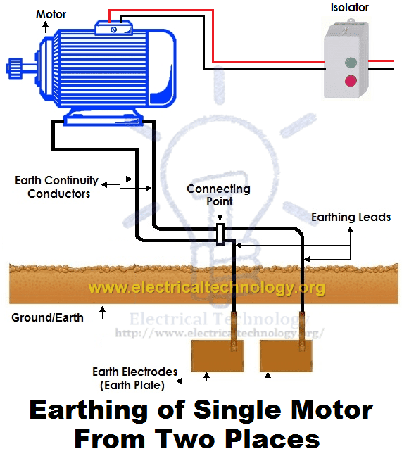
The frame of every generator, stationary motors and metallic parts of all transformers used for controlling energy should be earthed by two separate and yet distinct connections with the earth.
In a dc 3-wire system, the middle conductors should be earthed at the generating station.
Stay wires that are for overhead lines should be connected to earth by connecting at least one strand to the earth wires.
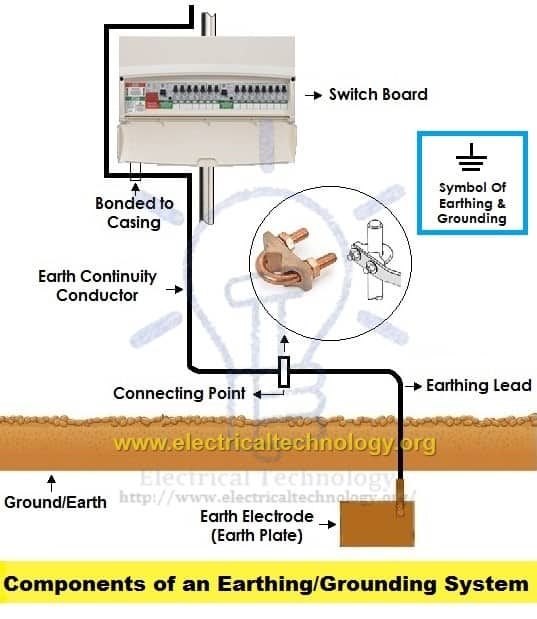
Components of Earthing System
A complete electrical earthing system consists on the following basic components.
Earth Continuity Conductor
Earthing Lead
Earth Electrode
Components of Electrical Earthing System
Earth Continuity Conductor or Earth Wire
That part of the earthing system which interconnects the overall metallic parts of electrical installation e.g. conduit, ducts, boxes, metallic shells of the switches, distribution boards,Switches, fuses, Regulating and controlling devices, metallic parts of electrical machines such as, motors, generators, transformers and the metallic framework where electrical devices and components are installed is known as earth wire or earth continuity conductor as shown in the above fig.
The resistance of the earth continuity conductor is very low. According to IEEE rules, resistance between consumer earth terminal and earth Continuity conductor (at the end) should not be increased than 1Ω. In simple words,resistance of earth wire should be less than 1Ω.
Size of the Earth Continuity Conductor or Earth Wire depends on thecable sizeused in thewiring circuit.
Size ofEarth Continuity Conductor
The cross sectional area of theEarth Continuity Conductorshould not be less than the half of the cross sectional area of the thickest wire used in theelectrical wiring installation.
Generally, the size of the bare copper wire used as earth continuity conductor is 3SWG. But keep in mind that, don’t use less than 14SWG as earth wire. Copper strip is also can be used as earth continuity conductor instead of bare copper wire but don’t go for it until manufacture recommend it.
Earthing Lead or Earthing Joint
The conductor wire connected between earth continuity conductor and earth electrode or earth plate is called earthing joint or “Earthing lead”. The point where earth continuity conductor and earth electrode meet is known as “connecting point” as shown in the above fig.
Earthing lead is the final part of the earthing system which is connected to the earth electrode (which is underground) through earth connecting point.
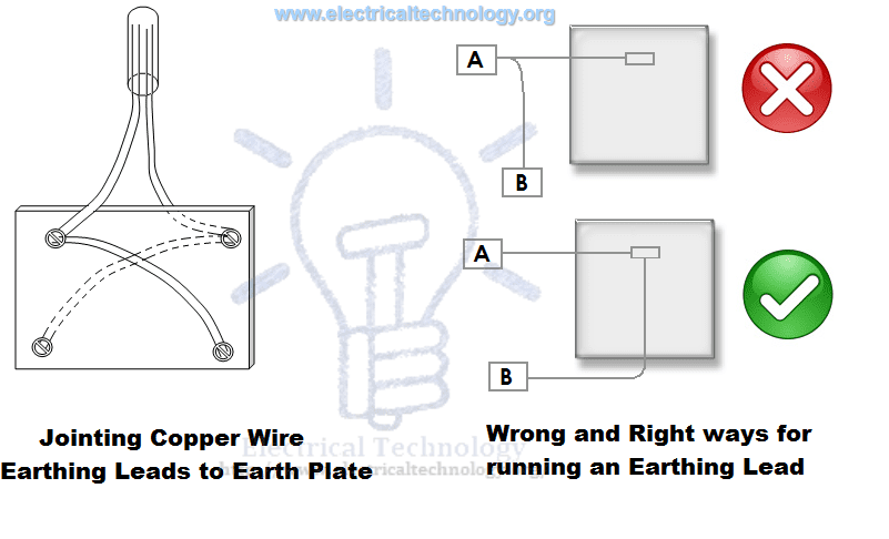
There should be minimum joints in earthing lead as well as lower in size and straight in the direction.
Generally, copper wire can be used as earthing lead but, copper strip is also used for high installation and it can handle the high fault current because of wider area than the copper wire.
A hard drawn bare copper wire is also used as an earthing lead. In this method, all earth conductors connected to a common (one or more) connecting points and then, earthing lead is used to connect earth electrode (earth plat) to the connecting point.
To increase the safety factor of installation, two copper wires are used as earthing lead to connect the device metallic body to the earth electrode or earth plate. I.e. if we use two earth electrodes or earth plats, there would be four earthing leads. It should not be considered that the two earth leads are used as parallel paths to flow the fault currents but both paths should work properly to carry the fault current because it is important for better safety.
Size of the Earthing Lead
The size or area of earthing lead should not be less than the half of the thickest wire used in the installation.
The largest size for earthing lead is 3SWG and the minimum size should not be less than 8SWG. If 37/.083 wire is used or the load current is 200A from the supply voltage, then it is recommended to use copper strip instead of double earthing lead. The earth lead connection methods is shown in the above fig.
Note: We will post additional article about Earth Plate size with simple calculations… Stay tune.
Earthing Electrode or Earth Plate
A metallic electrode or plate which is buried in the earth (underground) and it is the last part of the electrical earthing system. In simple words, the final underground metallic (plate) part of the earthing system which is connected with earthing lead is called earth plate or earth electrode.
A metallic plate, pipe or rode can be used as an earth electrode which has very low resistance and carry the fault current safely towards ground (earth).Size of Earthing Electrode
Both copper and iron can be used as earthing electrode.
The size of earth electrode (In case of copper)
2×2 (two foot wide as well as in length) and 1/8 inch thickness.. I.e. 2’ x 2’ x 1/8”. (600x600x300 mm)
In case of Iron
2’ x2’ x ¼” = 600x600x6 mm
It is recommended to bury the earth electrode in the moisture earth. If it is not possible, then put water in the GI (Galvanized Iron) pipe to make possible the moisture condition.
In the earthing system, put the earth electrode in vertical position (underground) as shown in the above fig. Also, put a 1 foot (about 30cm)layer of powdered charcoal and lime mixturearound the earth plate (don’t confuse with earth electrode and earth plate as both are the same thing).
This action makes the possible increase in the size of the earth electrode which leads a better continuity in the earth (earthing system) and also helps to maintain the moisture condition around earth plate.
P.S:We will post Example calculation about Earth Electrode Sizing… Stay tune.
Good to know:
Don’t use coke (after burning coal in the furnace to emit all the gases and other components, the remaining 88% carbon is called coke) or stone coal instead of charcoal (wood coal) because it causes to corrosion in the earth plate.
Since, the water level is different in the different areas; therefore, the depth for earth electrode installation is also different in various areas. But, the depth for earth electrode installation should not be less than 10ft (3 meter) and should below 1 foot (304.8mm) from the constant water level.
Motors,Generator,Transformersetc should be connected from to earth electrode two different places.
Earth Plate or Earth Electrode Size for Small installation
In small installation, use metallic rod (diameter = 25mm (1inch) and length = 2m (6ft) instead of earth plate for earthing system. The metallic pipe should be 2 meter below from the surface of ground. To maintain the moister condition, put 25mm (1inch) coal and lime mixture around the earth plate.
For effectiveness and convenience, you may use the copper rods 12.5mm (0.5 inch) to 25mm (1 inch) diameter and 4m (12ft) length. We will discuss the installation method of rod earthing latter.
Methods of Earthing | Types of Earthing
Earthing can be done in many ways. The various methods employed in earthing (in house wiring or factory and other connected electrical equipment and machines) are discussed as follows:
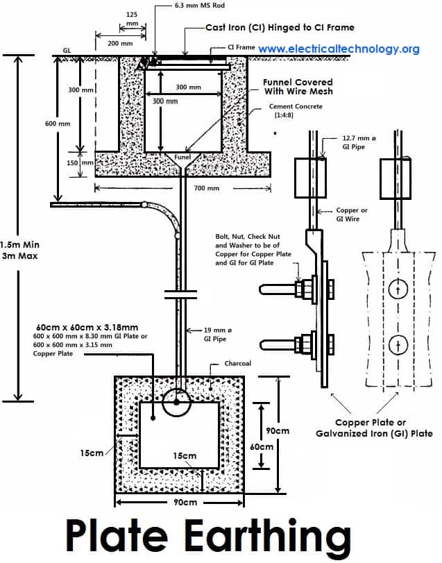
1). Plate Earthing:
In plate earthing system, a plate made up of either copper with dimensions 60cm x 60cm x 3.18mm (i.e. 2ft x 2ft x 1/8 in) or galvanized iron (GI) of dimensions 60cm x 60cm x 6.35 mm (2ft x 2ft x ¼ in) is buried vertical in the earth (earth pit) which should not be less than 3m (10ft) from the ground level.
For proper earthing system, follow the above mentioned steps in the (Earth Plate introduction) to maintain the moisture condition around the earth electrode or earth plate.
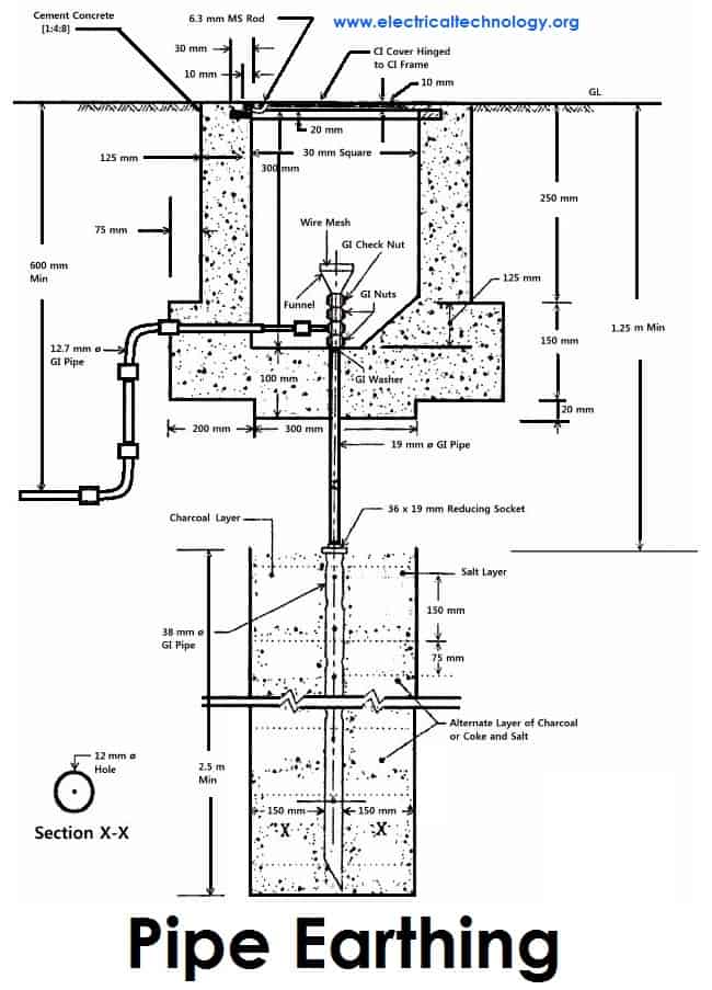
2). Pipe Earthing:
A galvanized steel and a perforated pipe of approved length and diameter is placed vertically in a wet soil in this kind of system of earthing. It is the most common system of earthing.
The size of pipe to use depends on the magnitude of current and the type of soil. The dimension of the pipe is usually 40mm (1.5in) in diameter and 2.75m (9ft) in length for ordinary soil or greater for dry and rocky soil. The moisture of the soil will determine the length of the pipe to be buried but usually it should be 4.75m (15.5ft).
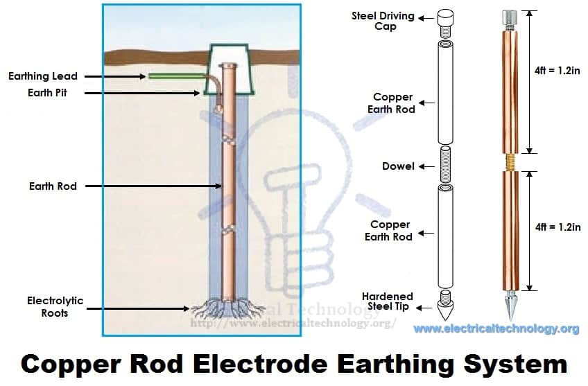
3). Rod Earthing
it is the same method as pipe earthing. A copper rod of 12.5mm (1/2 inch) diameter or 16mm (0.6in) diameter of galvanized steel or hollow section 25mm (1inch) of GI pipe of length above 2.5m (8.2 ft) are buried upright in the earth manually or with the help of a pneumatic hammer. The length of embedded electrodes in the soil reduces earth resistance to a desired value.
Copper Rod Electrode Earthing System
4). Earthing through the Waterman
In this method of earthing, the waterman (Galvanized GI) pipes are used for earthing purpose. Make sure to check the resistance of GI pipes and use earthing clamps to minimize the resistance for proper earthing connection.
If stranded conductor is used as earth wire, then clean the end of the strands of the wire and make sure it is in the straight and parallel position which is possible then to connect tightly to the waterman pipe.
5). Strip or Wire Earthing:
In this method of earthing, strip electrodes of cross-section not less than 25mm x 1.6mm (1in x 0.06in) is buried in a horizontal trenches of a minimum depth of 0.5m. If copper with a cross-section of 25mm x 4mm (1in x 0.15in) is used and a dimension of 3.0mm2if it’s a galvanized iron or steel.
If at all round conductors are used, their cross-section area should not be too small, say less than 6.0mm2if it’s a galvanized iron or steel. The length of the conductor buried in the ground would give a sufficient earth resistance and this length should not be less than 15m.
General method of Earthing / Proper Grounding Installation (Step by Step)
The usual method of earthing of electric equipments, devices and appliances are as follow:
First of all, dig a 5x5ft (1.5×1.5m) pit about 20-30ft (6-9 meters) in the ground. (Note that, depth and width depends on the nature and structure of the ground)
Bury an appropriate (usually 2’ x 2’ x 1/8” (600x600x300 mm) copper plate in that pit in vertical position.
Tight earth lead through nut bolts from two different places on earth plate.
Use two earth leads with each earth plate (in case of two earth plates) and tight them.
To protect the joints from corrosion, put grease around it.
Collect all the wires in a metallic pipe from the earth electrode(s). Make sure the pipe is 1ft (30cm) above the surface of the ground.
To maintain the moisture condition around the earth plate, put a 1ft (30cm) layer of powdered charcoal (powdered wood coal) and lime mixture around the earth plate of around the earth plate.
Use thimble and nut bolts to connect tightly wires to the bed plates of machines. Each machine should be earthed from two different places. The minimum distance between two earth electrodes should be 10 ft (3m).
Earth continuity conductor which is connected to the body and metallic parts of all installation should be tightly connected to earth lead.
At last (but not least), test the overall earthing system through earth tester. If everything is going about the planning, then fill the pit with soil. The maximum allowable resistance for earthing is 1Ω. If it is more than 1 ohm, then increase the size (not length) of earth lead and earth continuity conductors. Keep the external ends of the pipes open and put the water time to time to maintain the moisture condition around the earth electrode which is important for the better earthing system.
SI specification for Earthing
Various specifications in respect to earthing as recommended by Indian Standards are given below. Here are few;
An earthing electrode should not be situated (installed) close to the building whose installation system is being earthed at least more than 1.5m away.
The earth resistance should be low enough to cause the flow of current sufficient to operate the protective relays or blow fuses. It’s value is not constant as it varies with weather because it depends on moisture (but should not be less than 1 Ohm).
The earth wire and earth electrode will be the same material.
The earthing electrode should always be placed in a vertical position inside the earth or pit so that it may be in contact with all the different earth layers.
Dangers Of Not Earthing A Supply System
As emphasized on earlier, earthing is provided in order
To avoid electric shock
To avoid risk of fire as a result of earth leakage current through unwanted path and
To ensure that no current carrying conductor rises to a potential with respect to general mass of earth than its designed insulation.
However, if excessive current is not earthed, appliances will be damaged without the help of fuse in place. You should note that excessive current are earthed at their generating stations which is why earth wires carries very little or no current at all. It therefore implies that it is not necessary to earth any of the wires (live, earth and neutral wires) contained in a PVC. Earthing the live wire is catastrophic.
I have seen a person killed simply because a live wire got cut from overhead pole and fell to the ground while the ground was wet. Excessive current is earthed at generating stations and if at all the earthing is not efficient due to fault, earth fault interrupters will be there to help. Fuse help only when the power transmitted is above the rating of our appliances, it blocks the current from reaching our appliances by blowing off and protecting our appliances in the process.
In our electrical appliances, if excessive currents are not earthed, we would experience severe shock. Earthing takes place in electrical appliances only when there is a problem and it is to save us from danger. If in an electronic installation, a metallic part of an electrical appliance comes in direct contact with a live wire that results from maybe failure of installation or otherwise, the metal will be charged and static charge will accumulate on it.
If you happen to touch the metallic part at that moment you will be zapped. But if the metallic part of the appliance is earthed, the charge will be transferred to earth instead of accumulating on the metallic part of the appliance. Current don’t flow through earth wires in electrical appliances, it does so only when there is problem and only to direct the unwanted current to earth in order to protect us from severe shock.
In addition, if a live wire touches accidentally (in a faulty system) to the metallic part of a machine. Now, if a man touches that metallic part of the machine, then the current will flow through their body to the ground, hence, he will get shocked (electrocuted) which may lead to serious injuries even to death. That’s why earthing is so important?